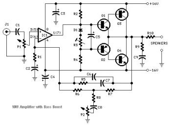
Here the 10W audio amplifier circuit based NE5532 and a couple of power transistor TIP41A/TIP42A
Component Parts:
P1 22K Log.Potentiometer P2 100K Log.Potentiometer R1 820R R2,R4,R8 4K7 R3 500R Trimpot R5 82K R6,R7 47K R9 10R R10 R22 4W Resistor (wirewound) D1 1N4148 IC1 NE5532 | C1,C8 470nF 63V C2,C5 100uF 25V C3,C4 470uF 25V C6 47pF 63V C7 10nF 63V C9 100nF 63V Q1 BC547B NPN Transistor Q2 BC557B PNP Transistor Q3 TIP42A PNP Transistor Q4 TIP41A NPN Transistor J1 RCA audio input socket |
This circuit is similar to the 18 Watt Audio Amplifier, and was intended mainly to satisfy the requests of correspondents unable to locate the TLE2141C chip. It works with the widespread NE5532 Dual IC but, obviously, its potential output will likely be comprised from the 9.5 - 11.5W range, since the voltage source rails can not exceed ±18V.
As amplifiers of this sort are commonly applied to drive small to medium sized loudspeaker cabinets, the bass frequency range is rather sacrificed. Therefore a bass-boost manage was inserted inside the feedback loop with the amplifier, so as to overcome this dilemma without having high quality losses. The bass lift curve can reach a maximum of +16.4dB @ 50Hz. In any situation, even when the bass control is rotated completely counterclockwise, the amplifier frequency response exhibits a gentle raising curve: +0.8dB @ 400Hz, +4.7dB @ 100Hz and +6dB @ 50Hz (referred to 1KHz).
10W Audio Amplifier Circuit Notes:
- The input can be immediately connected to CD players, tuners and tape recorders.
- Schematic exhibits left channel only, but C3, C4, IC1 as well as the power supply are typical to each channels.
- A log type for P2 will guarantee a far more linear regulation of bass-boost.
- Tend not to exceed 18 + 18V supply.
- Numbers in parentheses show IC1 proper channel pin connections.
- Q3 and Q4 has to be mounted on heatsink.
- D1 has to be in thermal contact with Q1.
- Set the volume manage for the minimum and R3 to its minimum resistance.
- Quiescent current (preferred measured with an multimeter in series with Q3 Emitter) is not crucial.
- Power-on the circuit and adjust R3 to read a electric current drawing of about 20 to 25mA.
- Wait about 15 minutes, keep an eye on if the electric current is varying and readjust if required.
- A right grounding is extremely necessary to remove hum and ground loops. Connect for the identical point the ground sides of J1, P1, C2, C3 &C4. Connect C9 to the output ground.
- Then connect separately the input and output grounds for the power source ground.


0 comments:
Post a Comment