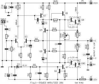
Here the 30W audio amplifier circuit for you who need a low power amplifier, but has good audio output quality and made from distinct components. The circuit design does not have any innovation. In the power stage is a Darlington pair of transistors packed TOP3, which can be screwed onto a heatsink, adding between them and the heatsink suitable leaves mica and ointment silicone for better dissipation of temperature.
The bias current regulation becomes with TR1, as follows. Place the ends of the resistors R20 and R21 terminals a multimeter 200mV scale and TR1 regulate late to get an indication 12mV. This voltage drop corresponds to a quiescent current 30mA. Allow the amplifier in this setting for 15 minutes without input signal and check again. If necessary correct the setting at 30mA.
Parts List:
| R1 = 1Kohm R2 = 47Kohm R3 = 1.5Kohm R4,R5 = 10Kohm R6 = 5.6Kohm R7 = 10ohm R8 = 47Kohm R9 = 560ohm R10,R11 = 8.2Kohm R12,R15 = 120ohm R13 = 680ohm R14 = 330ohm R16,R17 = 270ohm R18 = 22ohm 1W | R19 = NC R20,R21 = 0.39ohm 4W TR1 = 250ohm trimmer C1 = 470nF C2 = 1nF C3 = 68pF C4,C8 = 22nF C5,C6,C7 = 100nF C9 = 47uF/25V C10,C11 = 220uF/63V D1 = 9.1V 0.4W zener D2,D3 = 1N4148 Q1,Q2 = BC550C Q3 = MPSA56 |
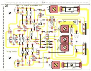
30W Audio Power Amplifier Top PCB Layout:
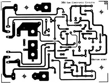
30W Audio Power Amplifier Bottom PCB Layout:


0 comments:
Post a Comment