Home »
Transistored Amplifier
» 50W Power Amplifier Circuit
50W Power Amplifier Circuit
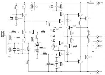
50W power amplifier circuit diagram using TIP33C and TIP34C power transistor. This easy power audio amplifier was originally developed for a circuit board workshop, conducted by the OSU IEEE Student Group. In the workshop, there are 20 participants and every participant constructed this amplifier, by etching and drilling the single sided circuit board, soldering all components, and attaching a pre-built heatsink assembly to the output transistors. Three workshops had been held in between 1995 to 1996. Although the schematic diagram is simple, this power amplifier have impressive audio performance, having a frequency response to approx 40 kHz, pretty low noise, reasonably fast slew rate, and approx 50 watts (real "RMS" power) using the appropriate +/- 40 volt unregulated power supply.
Note: The TIP33C and TIP34C have been discontinued and are usually not offered anyplace. Alternatively, replace the Q11=TIP33C and Q12=TIP34C with BD249C and BD250C.
Find the component part and power supply circuit diagram for this 50W Power Amplifier Circuit on this page.
About Audio Amplifier
An audio amplifier is an electronic amplifier that amplifies low-power audio signals (signals composed primarily of frequencies between 20 - 20 000 Hz, the human range of hearing) to a level suitable for driving loudspeakers and is the final stage in a typical audio playback chain.
The preceding stages in such a chain are low power audio amplifiers which perform tasks like pre-amplification, equalization, tone control, mixing/effects, or audio sources like record players, CD players, and cassette players. Most audio amplifiers require these low-level inputs to adhere to line levels.
While the input signal to an audio amplifier may measure only a few hundred microwatts, its output may be tens, hundreds, or thousands of watts. More explanation about power audio amplifier can be found at wikipedia.org


0 comments:
Post a Comment