Home »
Transistored Amplifier
» 60W Class-A Power Amplifier Circuit
60W Class-A Power Amplifier Circuit
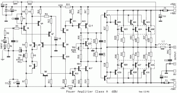
The circuit shows that each sub-amplifier consists of two stages of voltage gain. The first stage consists of two complementary stages in common emitter connection [Q1-7], whose profit is x2.3. The second stage is a current mirror stage [Q13-14] has load resistor that goes to 0V. The gain of this stage is x200. Consequently, the overall open-loop voltage gain is about x460 and so, since the closed loop gain is x26.7, the reduction due to negative feedback is x17.2 or 24db.
The input amplifiers are supplied with ± 15V from combinations of voltage regulators resistor-diode zener, R14-D1 and R21-D2. The current of the first stage [Q1] is 0.36mA [360], provided through a circuit "floats" [Q2-3], which provides simultaneous and necessary [and heat] stability at this stage. The gain of this stage is determined by the emitter resistor R6, which provides local negative feedback.
The second stage [Q4] is like a load of wiring cascode [Q5-6], the first has its base connected to 0V and the second is connected to the base line 15V. Consequently, minimizing the maximum variation of voltage in the collector's Q4, thereby reducing the capacity between the base-collector [phenomenon Miller], so that would reduce the bandwidth at high frequencies. The presence of Q5 and Q6 improves the bandwidth and linearity. As load Q6, is the second half [Q12] Current mirror and simulating as resistor in series with a properly biased diode. The next step after the mirror is a common emitter stage [Q16-17], which is a simple voltage amplifier.
Detailed information and explanation about this 60W Class-A power amplifier circuit, visit this page
About Audio Amplifier
An audio amplifier is an electronic amplifier that amplifies low-power audio signals (signals composed primarily of frequencies between 20 - 20 000 Hz, the human range of hearing) to a level suitable for driving loudspeakers and is the final stage in a typical audio playback chain.
The preceding stages in such a chain are low power audio amplifiers which perform tasks like pre-amplification, equalization, tone control, mixing/effects, or audio sources like record players, CD players, and cassette players. Most audio amplifiers require these low-level inputs to adhere to line levels.
While the input signal to an audio amplifier may measure only a few hundred microwatts, its output may be tens, hundreds, or thousands of watts. More explanation about power audio amplifier can be found at wikipedia.org


0 comments:
Post a Comment